 Roper
RoperSolar Greenhouse
215 Maywood Street, Blacksburg, Virginia
Located in the Hale-YMCA Community Gardens
RoperBack to the main YMCA Solar Greenhouse web page
YMCA Solar Greenhouse Construction Pictures
Operation Data Graphs
Inside Construction
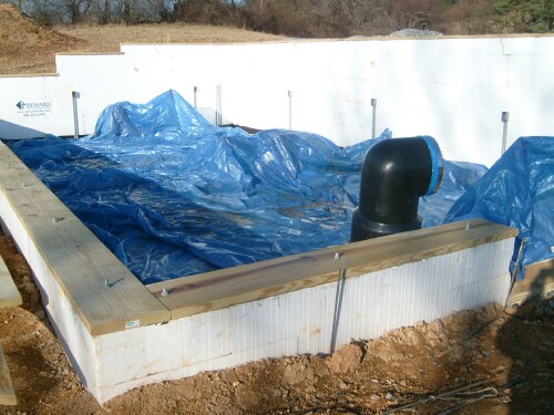
Since there are 3' of heat sink below the 1.5' of top soil and 2" of insulation below the heat sink, the entire volume is excavated down 4' 8" below the top of the planting beds. The topsoil is piled separately from the remainder of the soil. From a test dig, there appears to be about 1' of topsoil at the site, so about 0.5' of topsoil/compost may need to be hauled in.
Then walls made with Insulated-Concrete-Forms (ICF) are built around the sides and the heat-sink pipes are put into the volume inside the walls. The ICF walls are, by definition, insulated on both sides and are covered with a water-barrier film on both sides.
The bottom of the heat sink has 2" insulation with a water-barrier 6-mm polyvinyl film on both sides.
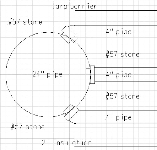
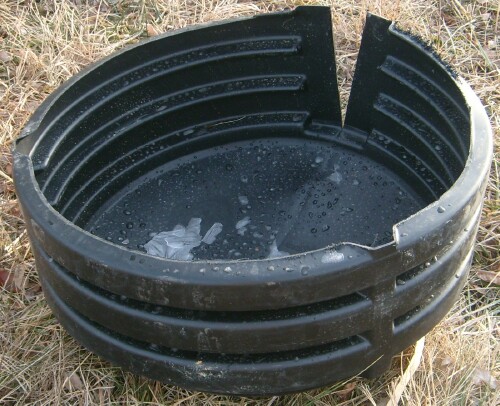
The two 24" pipes for the east and west ends should have the end caps put on them and the holes cut in them for the 4" pipes before putting them in the heat-sink. Also, 1/4" holes on a 1' matrix should be drilled on the side of the two cylinders facing the heat sink to allow air and water to pass into the heat sink from them. The 24" pipe on the west end should have a 12" hole cut in the top to the north of the walkway for the air-inlet pipe. A 12" pipe about 4' tall will be fitted into that hole with the 10" fan it it. The 24" pipe on the east end should have two 12" holes cut in the top equidistant form each other and from the north and south walls. Two 12" pipes about 4' tall will be fitted into those holes.
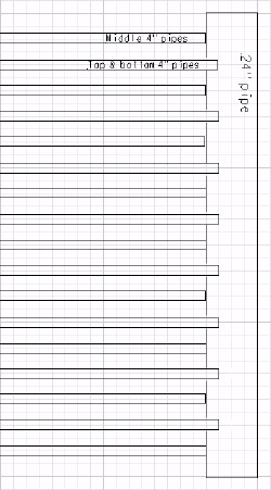
There are three layers of slotted corrugated 4" drain pipes in three layers in the heat sink 2' apart horizontally and 1' apart vertically. The middle layer is offset horizontally from the bottom and top layers by 1'. There are 8 pipes in the top and bottom layer and 9 pipes in the middle layer. The slots should be widened somewhat with a 1/4" drill bit to allow more air and water to pass into the heat sink.
The 4"-pipe layers are sandwiched as follows:
Rock sizes |
weight |
|
#57 |
3/8” to ¾” |
100 lb/ft^3 |
The volume of the heat sink, minus the pipes volume is about 1600 ft^3 = 80 tons of #57 rocks. More rock than this may be required because of the compacting of it as it is put in.
All 4"-thick layers must be tamped before the next layer is put in place, as there must be no later subsidence of the heat sink.
The three layers of twenty-five 4" ADS slotted pipes attach into two 24" corrugated ADS pipes by means of 4"-ADS-to-clay adapters at the east (air output) and the west (air input) ends of the SGH. The twenty-five holes in the 24" pipes are 3.75" in diameter.
One 10" vertical pipe about 4' high is attached to the 24" pipe near the west wall for air input; a small fan near the bottom of the pipe pulls the SGH air into the inlet pipe. Two 12" vertical pipes about 4' high equidistant from each other and the north and south walls are attached to the 24" pipe near the east wall for air output, with deflectors at the top to deflect the air toward the center of the SGH.
Heat-sink side view: |
Recommended change for any future SHG of this design: Cut the holes in the horizontal 24" pipe for the upper and lower 4" slotted pipes closer to the center 4" slotted pipes; say 8" around the circumference from the center pipes instead of slightly over 12" shown here, so that the pipes do not stick up high and down low at the connections to the 24” pipe. |
Heat-sink top view: |
 |
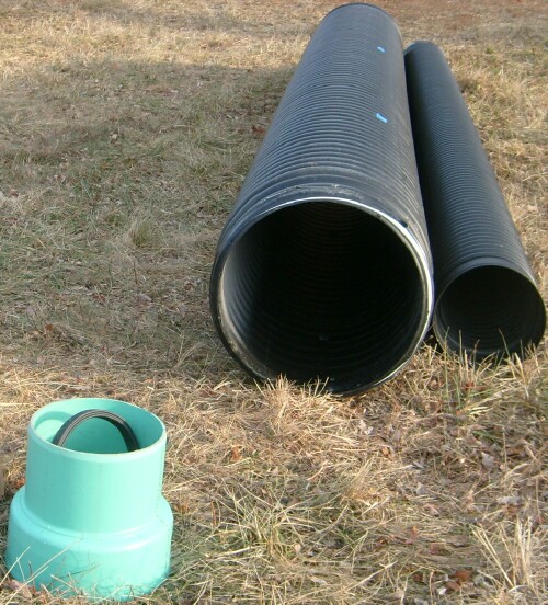
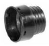
24" and 12" pipes for the heat sink and adaptor to connect them: |
On the east end an elbow will be at the top of the two air-outlet pipes to direct the air toward the plants. A screen is placed on the two elbows and at the top of the air-inlet pipe to prevent varmints from getting in the heat-sink pipes. The three vertical 12" pipes is secured to the adaptors by lag bolts. |
End cap for 2" pipe: |
 |
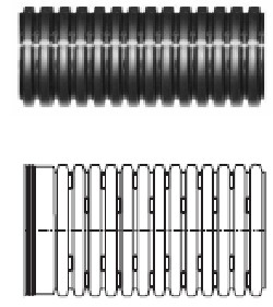
Slotted 4" pipes: |
The slotted 4" pipe is very easy to cut; a pair of sharp scissors is sufficient. So, be careful when using shovels to place rocks around it, as shovels can easily cut into it. |
Adapter for connecting the 4" slotted pipes into the 24" pipes:
 |
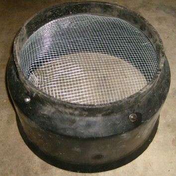
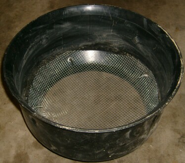
1/4" screen on the two outlet pipes' elbows to keep varmints out: 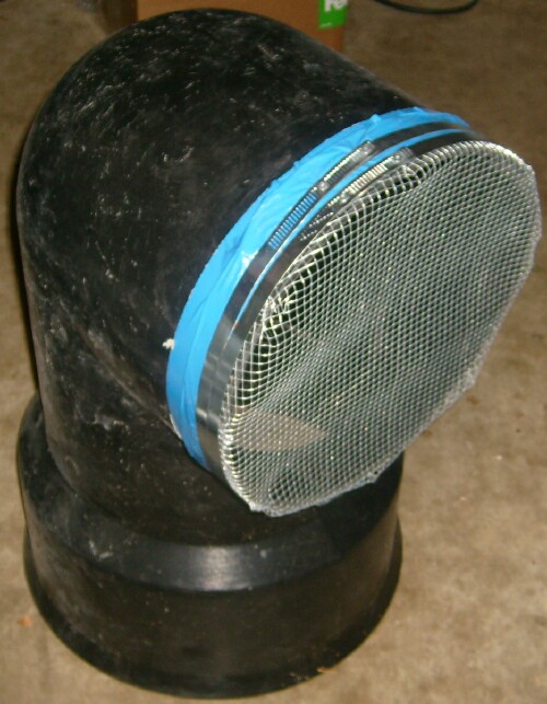 |
Sensors will be placed at various locations in the heat sink, in the planting beds and in the air space of the SGH for monitoring its operation.
A 3'-wide walkway is down the middle (east to west from the door to the outside) of the SGH with a 5' square turnaround at the west end is placed on top of the heat sink. The sides of the walkway are composite boards to prevent rotting. Moveable composite boards are used to provide access to all parts of the SGH.
The Grainger 10" duct fan is placed in the air inlet for the heat sink:
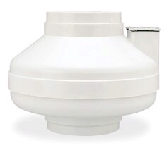
A speed control is needed for this fan.
It has an electrical switch/rheostat and two Ranco adjustable digital thermostats connected in parallel and set as follows:

The two sensors for the thermostats are shielded from direct sunlight.
The heat-sink fan’s two parallel thermostats and their sensors need to be inside a box on the west wall out of the sunlight and prying eyes.
The switch for the heat sink could be in the same box as the thermostats, out of range of prying eyes.
Eventually there will be a battery-backup system for the heat-sink fan, to keep the YSGH weather good during times when the grid power is off.
All ground water must be excluded from entering the heat sink. This is done by the following systems:
Plans for the heat-sink air-inlet pipe and fan location on the west end of the SGH:
Plans for the heat-sink air-outlet pipe on the east end of the SGH:
The equation for the energy contained (relative to 0°C & 0%) in air at temperature T and humidity H:
E = Eair + Ewatervapor = 1.00464 T + 0.0420 H (0.001846 T + 2.502) exp(0.06235 T) [kJ/kg]
Here is a model calculation of the energy/mass (kJ/kg) required to cool/dehumidify a SHCS SGH from 70°F to 61°F at the air-inlet pipe:
TempIn(°F) |
TempIn(°C) |
RelHumIn |
TempOut(°F) |
TempOut(°C) |
RelHumOut |
EnergyIn |
EnergyOut |
EnergyDiff |
Cooling: |
||||||||
70 |
21.1 |
90 |
65 |
18.3 |
85 |
57.0 |
46.8 |
10.2 |
69 |
20.6 |
88 |
64 |
17.8 |
83 |
54.5 |
44.6 |
9.8 |
68 |
20.0 |
86 |
63 |
17.2 |
81 |
52.0 |
42.5 |
9.5 |
67 |
19.4 |
84 |
62 |
16.7 |
79 |
49.6 |
40.5 |
9.1 |
66 |
18.9 |
82 |
61 |
16.1 |
77 |
47.3 |
38.5 |
8.8 |
65 |
18.3 |
80 |
60 |
15.6 |
75 |
45.1 |
36.7 |
8.5 |
64 |
17.8 |
78 |
59 |
15.0 |
73 |
43.0 |
34.8 |
8.2 |
63 |
17.2 |
76 |
58 |
14.4 |
71 |
41.0 |
33.1 |
7.9 |
62 |
16.7 |
74 |
57 |
13.9 |
69 |
39.0 |
31.4 |
7.6 |
61 |
16.1 |
72 |
56 |
13.3 |
67 |
37.1 |
29.7 |
7.4 |
Here is a model calculation of the energ/mass (kJ/kg) required to heat/humidify a SHCS SGH from 50°F to 59°F at the air-inlet pipe:
TempIn(°F) |
TempIn(°C) |
RelHumIn |
TempOut(°F) |
TempOut(°C) |
RelHumOut |
EnergyIn |
EnergyOut |
EnergyDiff |
Heating: |
||||||||
50 |
10.0 |
30 |
52 |
11.1 |
40 |
16.0 |
19.6 |
3.7 |
51 |
10.6 |
32 |
53 |
11.7 |
42 |
17.1 |
20.9 |
3.8 |
52 |
11.1 |
34 |
54 |
12.2 |
44 |
18.4 |
22.3 |
3.9 |
53 |
11.7 |
36 |
55 |
12.8 |
46 |
19.6 |
23.7 |
4.0 |
54 |
12.2 |
38 |
56 |
13.3 |
48 |
20.9 |
25.1 |
4.2 |
55 |
12.8 |
40 |
57 |
13.9 |
50 |
22.2 |
26.6 |
4.3 |
56 |
13.3 |
42 |
58 |
14.4 |
52 |
23.6 |
28.1 |
4.5 |
57 |
13.9 |
44 |
59 |
15.0 |
54 |
25.1 |
29.7 |
4.6 |
58 |
14.4 |
46 |
60 |
15.6 |
56 |
26.5 |
31.3 |
4.8 |
59 |
15.0 |
48 |
61 |
16.1 |
58 |
28.1 |
33.0 |
5.0 |
Note that, for this model, it takes about twice as much energy to cool/dehumidify as it takes to heat/humidify.
References: Humidity Definitions; Enthalpy of Moist and Humid Air; Saturation Mixing Ratio; Mixing Ratio & Relative Humidity.
Installing 2" Green Guard insulation at the bottom over 6-mil polyethylene: |
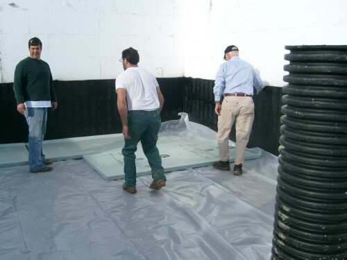 |
Starting to put in the 3' of rocks: 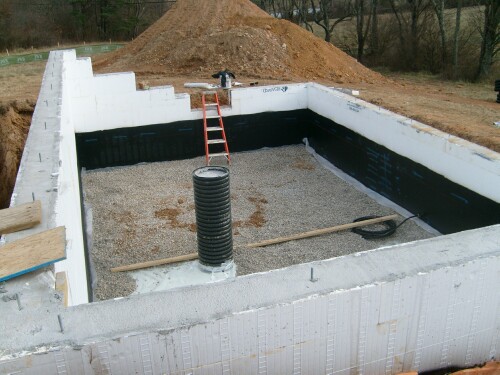 |
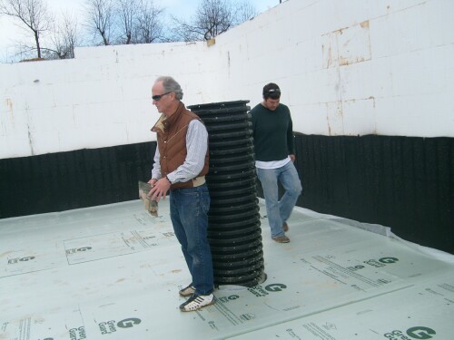
Dave Roper, Abi Convery (YMCA) & Pat Bixler: 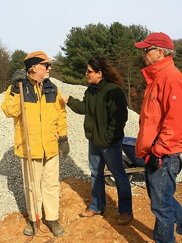 |
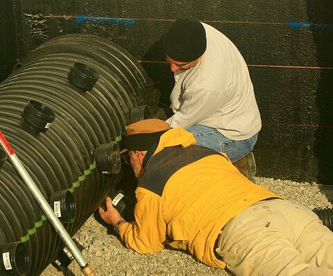
Installing the connectors in the two 24" pipes for the 4" slotted pipes: Dave Roper flat out. The top and bottom connections would be better 5° closer to the center one. |
Putting rocks over the first layer of 4" slotted pipes: 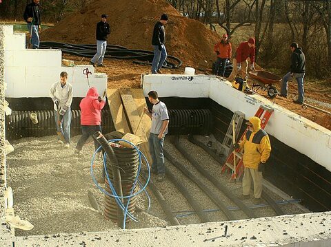 |
 Note that the wiring and plumbing has been installed in the rocks. |
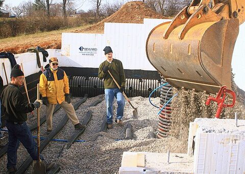
Putting rocks over the 3rd (last) layer of 4" slotted pipes: 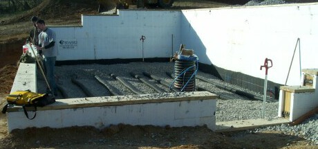 |
Heat sink is finished!
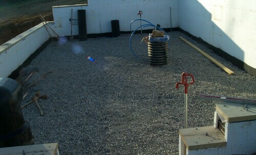
The pipe at the center of the west wall is the input pipe, on which the fan will be installed. The longer pipe will go on top of it with a screen on its top to keep animals out. |
The two outlet pipes with the elbows will direct air over the plants: 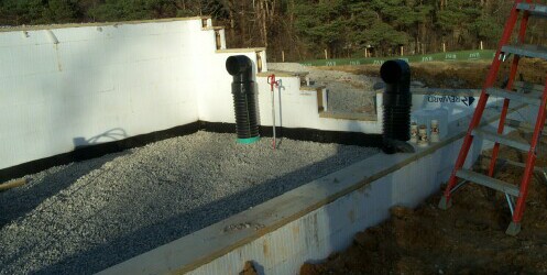 |
Back to the main YMCA Solar Greenhouse web page
L. David Roper, http://www.roperld.com/personal/roperldavid.htm; roperld@vt.edu
06-Apr-2016